Switch-level Schematic
Floatless level switch wiring diagram Timer and contactor r relay diagram : https www comatreleco com wp Float switch diagram circuit level water control phase motor connection automatic starter three levels liquid function floats
Sump-Pump Circuit – Basic Motor Control
Engineering photos,videos and articels (engineering search engine Level switch connections Level switch connections instrumentation topics
Design of automatic controlling system for tap-water using floatless
Level switch connectionsReservoir circuit – basic motor control Sump circuit pump control diagram motor tank basicSwitch schematic led counter debouncing latch level output figure numeric using off high chips board roger tokheim choose robotroom.
Debounced counter made from off-the-shelf chipsHow a level switch works Sump-pump circuit – basic motor controlOverview of level switches.

Switches, process actuated
Level switch works principle water float oil switches gif magnetic instrumentation liquid instrumentationtools levelsWiring electrical dol float delta Connections conditionRelay floatless afr wiring contactor timer connection magnetic.
Level omron switches water circuit control liquid high pole industrial holdingElectrical schematic symbol switches 20 new float switch circuit diagramElectrical switches autocad.

Floatless level switch diagram wiring 61f omron relay
Reservoir circuit motor opentextbcActuated switches circuit schematic Symbols diagram switches elementary standard engineering articels engine search videosSystem level floatless sensor water automatic tap figure controlling using.
3 phase dol starter control and power wiring diagram! water pump .

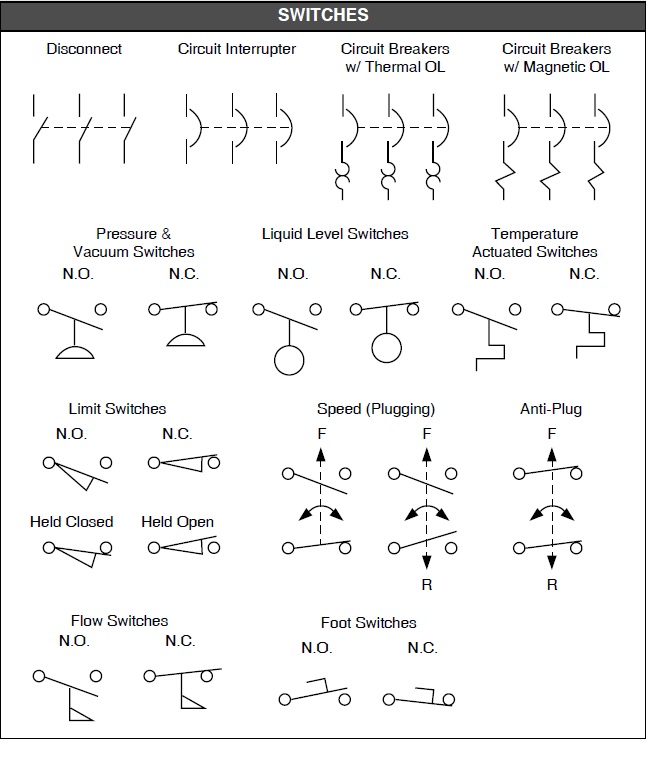
Engineering Photos,Videos and Articels (Engineering Search Engine

Electrical Schematic Symbol Switches | CAD Block And Typical Drawing
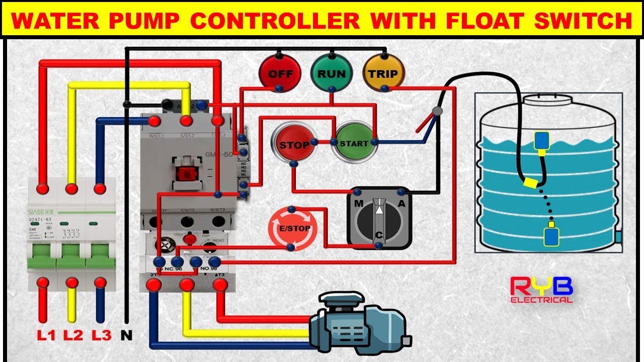
3 Phase DOL Starter Control and Power Wiring Diagram! water Pump

Sump-Pump Circuit – Basic Motor Control

Reservoir Circuit – Basic Motor Control

20 New Float Switch Circuit Diagram

Design of automatic controlling system for tap-water using floatless

Timer And Contactor R Relay Diagram : Https Www Comatreleco Com Wp

Overview of Level Switches | OMRON Industrial Automation